

ACP-01101 PDF試験材料2023年最新の実際に出るACP-01101問題集
更新されたのはAutodesk ACP-01101問題集PDFオンラインエンジン
AutodeskのACP-01101試験は、AutoCADドラフトとデザインのスキルと知識を評価する認定テストです。AutoCADは、建築家、エンジニア、デザイナーが2Dおよび3D図面を作成および編集するために使用されるコンピュータ支援設計(CAD)ソフトウェアです。この試験は、ソフトウェアを使用して正確で高品質なデザインを作成する専門家の熟練度をテストするように設計されています。
ドラフトと設計のためにAutoCADのAutodesk認定プロフェッショナルになるには、候補者はACP-01101試験に合格する必要があります。これは、2時間の制限時間以内に完了する必要がある35の質問で構成されています。試験はコンピューターベースであり、認定テストセンターまたはオンラインで撮影できます。候補者は、試験に合格するには、70%以上のスコアを達成する必要があります。
Autodesk ACP-01101 認定を取得することは、AutoCAD の図面作成および設計に高度な熟練度を持っていることを示すものです。この認定は、図面作成および設計業界でキャリアアップを目指すプロフェッショナルにとって、貴重な資産となります。また、認定されたプロフェッショナルをチームに迎えることで、雇用主はAutoCAD の質と熟練度に対する取り組みを示すことができます。
質問 # 15
Refer to the exhibit.
When working on this part created with AutoCAD solids, the dimensions of the shaded planes need to be established.
Which U'CS shows the correct size and shape of the shaded planes?
- A. Face
- B. Vertical
- C. View
- D. World
正解:A
解説:
Explanation
The UCS is a moveable Cartesian coordinate system that establishes the XY work plane, horizontal and vertical directions, axes of rotation, and other useful geometric references1. You can change the UCS origin and orientation for convenience as you specify points, enter coordinates, and work with drawing aids1.
The face option sets a new UCS based on a selected face of a 3D solid object2. This option will align the XY plane of the UCS with the selected face and show its correct size and shape2.
質問 # 16
You have three multileaders as shown in exhibit 1. (Refer to the exhibit 1 tab.)
You need to change the display of the multileaders to match the multileaders in exhibit. (Refer to the exhibit 2 tab.)
Which command should you use?
- A. Align Leader
- B. Add Leader
- C. Remove Leader
- D. Collect Leader
正解:D
解説:
Explanation
The command that you should use is B. Collect Leader1. The collect leader option groups multiple leaders into one multileader object with a common landing line1. This option is useful when you want to create a single label or callout for multiple objects2.
To use this option, you need to select the MLEADER command and then select Collect Leader from the Options menu. Then you can select two or more existing multileaders that have similar properties and press Enter. The selected multileaders will be collected into one multileader object with a common landing line1.
質問 # 17
You have the drawing shown in the exhibit.
You are using the DIM command to preview suitable dimension type objects in the drawing.
Which dimension type will appear when you hover over each object? Select the appropriate dimension type from each of the drop-down lists.
正解:
解説:
* When you hover over the arc (1), you will see a radius dimension type preview.
* When you hover over the circle (2), you will see a diameter dimension type preview.
* When you hover over the horizontal line (3), you will see a horizontal linear dimension type preview.
* When you hover over the angled line (4), you will see an angular dimension type preview.
質問 # 18
You want to print a copy of a floor plan with all the interior objects hidden. You already have a polyline drawn around the footprint of the plan.
Complete the statements by selecting the correct option from the drop-down,lists.

正解:
解説:
Explanation
BOX 1 = WIPEOUT command with the Polyline option2.BOX2 = DRAWORDER command23
https://forums.autodesk.com/t5/autocad-forum/polyline-plan-view-boundary-of-point-cloud/td-p/6251860
質問 # 19
You need to create a hatch pattern that looks the same regardless of the viewport scale.
What should you do?
- A. Create an associative hatch
- B. Set the default hatch pattern
- C. Create an annotative hatch
- D. Set the current hatch scale by using the HPSCALE system variable
正解:C
解説:
Explanation
an annotative hatch is a hatch that automatically adjusts its scale and size to match the viewport scale. This means that the hatch pattern will look the same regardless of how you zoom in or out of the viewport.
To create an annotative hatch, you need to:
* Set the annotation scale tool to 1:1
* Create your hatch as usual
* In the properties palette, make the hatch annotative
* Add annotation scales to the hatch as needed
This will create a hatch that displays correctly at different viewport scales.
https://forums.autodesk.com/t5/autocad-forum/annotative-hatch/td-p/2651268
質問 # 20
When you create an attribute definition, which mode should be used if you want the default value of the attribute assigned upon insertion where the attribute value cannot be changed?
Note Exhibit shown is the AutoCAD interface in Windows While the AutoCAD for Mac version differs in appearance, the correct answer correlates in the options.
- A. Constant
- B. Verify
- C. Preset
- D. Lock position
正解:A
解説:
Explanation
the mode that should be used if you want the default value of the attribute assigned upon insertion where the attribute value cannot be changed is Constant. This option sets the attribute value as constant and prevents it from being modified during a block insertion or later.
https://knowledge.autodesk.com/support/autocad/learn-explore/caas/CloudHelp/cloudhelp/2015/ENU/AutoCAD
質問 # 21
What should be typed at the command line in order to start creating a line for drawing reference that starts at a defined point and extends to infinity in the designated direction?
- A. XLINE
- B. CURSORSIZE
- C. RAY
- D. MLINE
正解:A
解説:
Explanation
According to the AutoCAD for Design and Drafting documents1, the command that should be typed at the command line in order to start creating a line for drawing reference that starts at a defined point and extends to infinity in the designated direction is XLINE2. This command creates a construction line, which is a type of reference line that can help you manage accurate parameters of your drawing2. You can also use point objects as nodes or reference geometry for object snaps and relative offsets3.
質問 # 22
You need to change the width of a specific polyline without affecting the width of the other polylines in a drawing.
What should you use?
- A. The PLINEWID system variable
- B. The LWEIGHT command
- C. The PEDIT command
- D. The PLINEGEN system variable
正解:C
解説:
Explanation
polyline is a connected sequence of line segments created as a single object that can contain a width. You can change the width of a polyline by using the PEDIT command.
Based on 3 and 4, LWEIGHT is a command that sets the current lineweight, which is used for new objects and affects objects in the current space only. PLINEWID is a system variable that sets a default polyline width for new polylines. PLINEGEN is a system variable that controls how linetype patterns are generated around vertices.
https://www.roadlesstraveledstore.com/how-do-i-change-the-width-of-a-polyline-in-autocad/
https://knowledgeburrow.com/how-do-i-change-the-width-of-a-polyline-in-autocad/
質問 # 23
You plan to draw a line at an angle of 6.25 degrees.
Where in the user interface do you configure polar tracking to work at this angle after selecting Polar Tracking On?
Note: Exhibit shown is the AutoCAD interface in Wind. Which the AutoCAD for the Mac version differs in appearance, the correct answers correlate in the options.
正解:
解説:
See the answer below:
Explanation
polar tracking is a feature that allows you to draw lines at specific angles. You can configure polar tracking to work at any angle you want by following these steps:
* Click on the arrow next to the Polar Tracking icon in the Status bar and select Settings.
* In the Drafting Settings dialog box, click on the Polar Tracking tab.
* Under Additional Angles, click on New and enter 6.25 as the angle value. Click OK.
* Make sure that 6.25 is checked in the list of additional angles. Click OK.
Now you can draw a line at an angle of 6.25 degrees by using polar tracking.
質問 # 24
You have two viewports at different viewport scales as shown in the exhibit. The geometry and dimensions were created in model space.
The viewport scales are 1 16 and 1:5. The dimension text height is the same for both viewports in the layout.
Evaluate the graphic and complete the statements by selecting the correct options from the drop-down lists.

正解:
解説:
Explanation
Box 1 = annotative
an annotative dimension style is a dimension style that automatically adjusts the size of dimensions based on the viewport scale. An annotative dimension style has an icon next to its name in the Dimension Style Manager dialog box. The dimension style is annotative because the dimension text height is the same for both viewports in the layout, even though they have different viewport scales1.
Box 2 = associativeThe DIMASSOC is at its default value of 2, therefore the dimensions are associative because they are linked to and update with the measured geometry3.
質問 # 25
In model space (MODEL), a room label text height is set to 300 mm in the designated text style.
Which viewport scale should you apply to a layout viewport (PAPER) so that the room label text height will display as 3 mm when plotting the drawing?
- A. A custom viewport scale
- B. 1:100
- C. 100:1
- D. 1:1
正解:C
解説:
Explanation
the formula for determining object scaling is:
Object Height x Annotation Scale x Annotation Plot Size = Model Space or Paper Space Height In this case, we want the room label text height to be 3 mm in paper space when plotting the drawing.
Assuming an annotation plot size of 1 mm and an object height of 300 mm, we can solve for the annotation scale as follows:
300 x Annotation Scale x 1 = 3 Annotation Scale = 3 / 300 Annotation Scale = 0.01 Therefore, the viewport scale that corresponds to this annotation scale is B. 100:1.
https://knowledge.autodesk.com/support/autocad-architecture/learn-explore/caas/CloudHelp/cloudhelp/2016/EN
質問 # 26
You have the drawing shown in the exhibit.
You need to place the polygon and the rectangle on the same layer as the circle.
Which command should you use to complete the task in the least number of steps?
- A. Match Properties
- B. Make Current (LAYMCUR)
- C. ByLayer
- D. Copy
正解:A
解説:
Explanation
match properties is a command that allows you to apply the properties of one object to another object. You can use this command to change the layer of an object by selecting an object on the desired layer as a source.
To use this command, you can either:
* Click on the Match Properties icon in the Properties panel of the Home tab.
* Type MATCHPROP at the command prompt and press Enter.
Then, you can follow these steps:
* Select an object on the same layer as the circle as a source object and press Enter.
* Select the polygon and the rectangle as destination objects and press Enter.
Now you have placed the polygon and the rectangle on the same layer as the circle.
質問 # 27
You are using the HATCH command in a drawing. You select the internal point that corresponds with the X as shown in the following exhibit.
Move each setting from the list on the left to the corresponding result on the right.
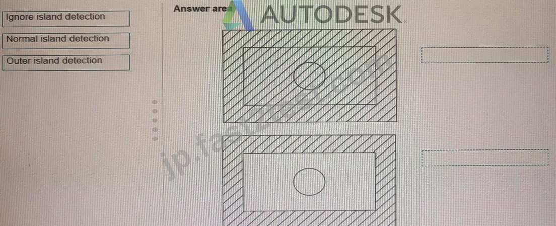
正解:
解説:
Explanation
Box 1 = ignore island detection
Box 2 = Outer island detection
https://knowledge.autodesk.com/support/autocad/learn-explore/caas/CloudHelp/cloudhelp/2021/ENU/AutoCAD
質問 # 28
Refer to the exhibit.
You are working on a drawing. You copy a set of entities and exit the COPY command. You then use the MOVE command on the same set of entities.
Which default option should you use when prompted to select entities?
- A. P (Previous)
- B. A (All)
- C. L (Last)
- D. Spacebar
正解:A
解説:
Explanation
when you use the MOVE command on a set of entities that you have previously copied, you should use B. P (Previous) as the default option when prompted to select entities. This will select the last set of entities that you modified with any command.
https://forums.autodesk.com/t5/autocad-forum/move-previous-command/td-p/3466896
https://www.cadlinecommunity.co.uk/hc/en-us/articles/360002360178-Move-Copy-Rotate-All-in-one-editing-co
質問 # 29
In which order should you perform the actions to rotate square (1) to match the angle of square (2).
Move all actions to the answer area and place them in the correct order.

正解:
解説:
Explanation
rotate is a command that rotates selected objects around a base point to an absolute angle. You can specify the base point and the rotation angle by entering values or selecting points. You can also use the reference option to align objects with other objects.
* 1- Start the Rotate command, select the square, and press Enter
* 4- Specify the base point
* 5- Select the Reference option
* 3- Select the lower left corner and the lower right corner as the first and second points of the reference angle
* 2- Enter a value of 0 for the new angle and press Enter
質問 # 30
You have the office arrangement shown in exhibit 1. (Refer to the exhibit 1 tab.)
You need a mirror line to create the right-hand office arrangement shown in exhibit 2. (Refer to the exhibit 2 tab.)
Which tool would you use to make sure the mirror line is centered between the two wall lines without adding additional linework?
- A. Endpoint (END)
- B. Mid Between Two Points (M2P)
- C. Intersection (INT)
- D. Midpoint (MID)
正解:B
解説:
Explanation
https://www.tutorial-autocad.com/mirror-command
http://docs.autodesk.com/ACD/2011/ENU/filesMDG/WS1a9193826455f5ff2566ffd511ff6f8c7ca-3f53.htm
質問 # 31
You need to snap to the centroid of a closed polyline.
Which Object Snap mode should you use? Click the correct option in the answer area.
Note: Exhibit shown is the AutoCAD interface in Windows. While the AutoCAD for MAc version differs in appearance, the correct answer correlates in the options.
正解:
解説:
Explanation
object snaps are modes that allow you to snap to specific points on objects. To snap to the centroid of a closed polyline, you should use the Geometric Center object snap mode. This mode will display an asterisk (*) marker when you move the cursor over the geometric center of a closed polyline or spline.
To use this mode, you can either:
* Click on the Object Snap icon in the Status bar and select Geometric Center from the menu.
* Type GCE at the command prompt or when prompted for a point and press Enter.
Now you can snap to the centroid of a closed polyline by using Geometric Center object snap.
質問 # 32
Select whether each statement is True or False.
正解:
解説:
Explanation
True
1. According to the AutoCAD for Design and Drafting documents1, a polyline is a connected sequence of line segments created as a single object. You can create straight line segments, arc segments, or a combination of the two2341. Therefore, the correct answer is True. A polyline can include both straight line segments and arc segments.
2. False.According to the AutoCAD for Design and Drafting documents1, a spline is a smooth curve that passes through or near a set of fit points, or that is defined by the vertices in a control frame. A spline does not have a constant radius, but rather a local radius at each point on the curve2. Therefore, AutoCAD cannot directly dimension or display a radius of a spline curve23. You can use some workarounds such as exploding the curve to arc segments with the FLATTEN command2, or creating a polyline over the top with arc active3, but these may not be accurate or desirable. Therefore, the correct answer is False. The radius on a spline cannot be found in AutoCAD properties.3. TrueAccording to the AutoCAD for Design and Drafting documents1, a 2D polyline is a connected sequence of line segments created as a single object. You can specify an elevation for a 2D polyline using the Edit Polyline Elevations command2. However, this command will assign the same elevation to all vertices of the polyline2. Therefore, you cannot assign different elevations to different segments or points of a 2D polyline. Therefore, the correct answer is True. You can assign only one elevation to a 2D polyline.
質問 # 33 
The exhibit shows a workstation arrangement, with horizontal and vertical dimensions, representing the row and column spacings.
Both dimensions have been placed incorrectly, with one origin point of each dimension being placed in the wrong position.
What command should be used to ensure that the dimension objects are placed accurately?
- A. Break (D1MBREAK)
- B. Reassociate (DIMREASSOCIATE)
- C. Inspect (DIMINSPECT)
- D. Adjust Space (DIMSPACE)
正解:B
解説:
Explanation
According to the AutoCAD for Design and Drafting documents1, the command that should be used to ensure that the dimension objects are placed accurately is Reassociate (DIMREASSOCIATE)2. This command associates or reassociates selected dimensions to objects or points on objects3. You can also control whether new dimensions are associative by checking the option Make New Dimensions Associative in the User Preferences tab4.
質問 # 34
You place a red rectangular polyline over a PDF underlay in a drawing, and then use the rectangular polyline as a clipping boundary. The result is shown in the exhibit.
Select whether each statement is True or False.

正解:
解説:
Explanation
False: You cannot create a new clipping boundary without removing the existing clipping boundary. If you want to change the clipping boundary, you have to select the PDF underlay, right-click and choose Remove Clipping Boundary first, and then use the Clip PDF command again with a different option12.
True: To access the Underlay Layers dialog box, you have to select a PDF underlay, right-click and choose PDF Layers2. In the Underlay Layers dialog box, you can click the light bulb icon for the layer name that you want to turn on or off2.
True: To use the Align command, you have to select a polyline, right-click and choose Align3. Then you have to specify two source points on the polyline and two destination points on the PDF underlay that correspond to each other3. You can also specify a third pair of points if needed3. Finally, you have to press Enter twice to confirm the alignment3. The statement "You can use the grips on the polyline to align to the edges and corners of the PDF underlay" is true. When you place a rectangular polyline over a PDF underlay and use it as a clipping boundary, the polyline's grips can be used to adjust its size and position so that it aligns with the edges and corners of the underlay.
By hovering the cursor over a grip, you can see its tooltip display the name of the grip and its function. If you then click and drag the grip, you can move it along its corresponding axis to resize the boundary. This allows you to adjust the clipping boundary to fit exactly over the content you want to display.
質問 # 35
......
Autodesk ACP-01101問題集PDFのベストを目指すなら問題集を使おう 目指そう高得点:https://jp.fast2test.com/ACP-01101-premium-file.html
ACP-01101.PDFで問題解答PDFサンプル問題は信頼され続ける:https://drive.google.com/open?id=1hITruGtkHXCcIBAY5Ub6nVM37x-EpOV3