

検証済みACP-01101問題集と解答で2023年最新のACP-01101をダウンロード
更新された100%カバー率リアルACP-01101試験問題で100%合格保証付いてます
認定試験は、コンピュータ支援設計(CAD)ソフトウェアを開発することに特化した主要なソフトウェア企業である Autodesk によって提供されています。Autodesk は、AutoCAD、Revit、Inventor など、自社のソフトウェアを使用するプロフェッショナル向けに一連の認定試験を提供しています。Autodesk ACP-01101 認定試験は同社が提供する最も人気のある認定試験の1つであり、AutoCAD の熟練度の基準として世界的に認められています。
質問 # 23
Drawings from different sources have been combined and resulted in duplicate background elements that are slightly offset from each other Some of the layer names match and other layers have an E prefix, indicating that they are existing.
To clean up the drawing, the Overkill (OVERKILL) command is used.
Which two settings will resolve the duplicate background and offsetting issues? (Select 2)
- A. Ignore Transparency
- B. Maintain associative objects
- C. Ignore Color object property
- D. Tolerance value
- E. Ignore Layer object property
正解:D、E
解説:
Explanation
You need to ignore layer object property to remove duplicates that have different layer names but are otherwise identical4. You also need to set a tolerance value that is larger than the offset distance between the objects5.
質問 # 24
You need to configure the layout viewports shown in the exhibit.
Which three methods can you use to create the viewports in a layout tab? (Select 3)
- A. Clip a viewport to multiple different shapes by using the VPCLIP command.
- B. Create individual viewports by using the MVIEW command.
- C. Create a new page setup.
- D. From the View Manager dialog box, generate named views and add them as layout viewpoints.
- E. From the Viewports dialog box: select a viewport configuration.
正解:B、D、E
解説:
Explanation
a layout viewport is a window that displays a view of model space on a layout tab. You can create multiple layout viewports to display different views of your model at different scales.
To create the viewports in a layout tab, you can use three methods:
* From the Viewports dialog box: select a viewport configuration
* Create individual viewports by using the MVIEW command
* From the View Manager dialog box, generate named views and add them as layout viewpoints These methods will allow you to create and arrange viewports on your layout tab.
https://knowledge.autodesk.com/support/autocad/learn-explore/caas/CloudHelp/cloudhelp/2018/ENU/AutoCAD
質問 # 25
With an associative array selected as shown in the exhibit, which command will separate the objects into individual objects?
- A. Explode
- B. Ungroup
- C. Disassociate
- D. Break
正解:A
解説:
Explanation
array items are contained in a single array object, similar to a block. You can change the number of these items and their spacing in an associative array.
Based on 2, you can move an item in an associative array by pressing and holding the Ctrl key, and then selecting the items you want to move.
since explode is the command that separates objects into individual objects. Disassociate, ungroup and break are not valid commands for associative arrays.
https://knowledge.autodesk.com/support/autocad/learn-explore/caas/CloudHelp/cloudhelp/2020/ENU/AutoCAD
質問 # 26
A site plan was recently modified to relocate a building to a new location While relocating the building, only the hatch location of the building was moved by mistake as shown in the exhibit.
Evaluate the graphic and answer each question by selecting the correct options from the drop-down lists.

正解:
解説:
Explanation
Box 1 = Turn on Associative Hatching
Box 2 = use the Recreate Boundary option from Hatch Editor
https://knowledge.autodesk.com/support/autocad/troubleshooting/caas/sfdcarticles/sfdcarticles/Recreating-hatch-
https://knowledge.autodesk.com/support/autocad/learn-explore/caas/CloudHelp/cloudhelp/2018/ENU/AutoCAD
質問 # 27 
You have a line segment that is 150 units long as shown in the exhibit.
You need the line to be 200 units long without adding any additional linework. The leftmost end of the line must remain in the current position.
What should you do?
- A. From the Edge Extension option of the Extend command, enter 50 units, and then select the right end of the line
- B. From the Delta option of the Lengthen command, enter 50! units and then select the right end of the line
- C. From the Delta option of the Lengthen command, enter 200 units and then select the right end of the line
- D. From the Project option of the Extend command, enter 50 units, and then select the right end of the line.
正解:B
解説:
Explanation
From the Delta option of the Lengthen command, enter 50 units and then select the right end of the line. This way, you can increase the length of the line by 50 units from its current endpoint without changing its direction or position2
https://www.learnvern.com/autocad-tutorial-in-hindi/how-to-use-lengthen-command
質問 # 28
You have the drawing shown in the exhibit.
You need to place the polygon and the rectangle on the same layer as the circle.
Which command should you use to complete the task in the least number of steps?
- A. Make Current (LAYMCUR)
- B. Match Properties
- C. ByLayer
- D. Copy
正解:B
解説:
Explanation
match properties is a command that allows you to apply the properties of one object to another object. You can use this command to change the layer of an object by selecting an object on the desired layer as a source.
To use this command, you can either:
* Click on the Match Properties icon in the Properties panel of the Home tab.
* Type MATCHPROP at the command prompt and press Enter.
Then, you can follow these steps:
* Select an object on the same layer as the circle as a source object and press Enter.
* Select the polygon and the rectangle as destination objects and press Enter.
Now you have placed the polygon and the rectangle on the same layer as the circle.
質問 # 29
Refer to the exhibit.
You are working on a drawing. You copy a set of entities and exit the COPY command. You then use the MOVE command on the same set of entities.
Which default option should you use when prompted to select entities?
- A. A (All)
- B. P (Previous)
- C. Spacebar
- D. L (Last)
正解:B
解説:
Explanation
when you use the MOVE command on a set of entities that you have previously copied, you should use B. P (Previous) as the default option when prompted to select entities. This will select the last set of entities that you modified with any command.
https://forums.autodesk.com/t5/autocad-forum/move-previous-command/td-p/3466896
https://www.cadlinecommunity.co.uk/hc/en-us/articles/360002360178-Move-Copy-Rotate-All-in-one-editing-co
質問 # 30
You need to convert the two sets of parallel lines shown in 1 into the objects shown in 2 without repeating the command.
What should you use?
- A. The CHAMFER command with the Polyline option
- B. The FILLET command with the Polyline option
- C. The CHAMFER command with the Multiple option
- D. The FILLET command with the Multiple option
正解:C
解説:
Explanation
According to the AutoCAD for Design and Drafting documents, the CHAMFER command creates a beveled corner between two lines, while the FILLET command creates a rounded corner between two lines. Both commands can be used with the Polyline option to apply chamfers or fillets to all corners of a 2D polyline1.
However, in this case, the lines are not polylines but separate line segments. Therefore, using the Polyline option will not work. Instead, you can use the Multiple option to chamfer or fillet multiple sets of lines without restarting the command2.
質問 # 31
A block entity in the current drawing needs to be converted to a new drawing file of its own.
Which command should be used?
- A. BSAVEAS
- B. BLOCK
- C. BEDIT
- D. WBLOCK
正解:D
解説:
Explanation
the command that should be used to create a new drawing file from selected objects is WBLOCK. This command allows you to export a group of objects as a drawing, which can be inserted into other drawings as a block2.
質問 # 32
You start the EXTEND command.
You need to be able to trim several objects quickly without exiting the EXTEND command.
What should you do?
- A. Hold the Shift key while selecting the objects.
- B. Hold the Alt key while selecting the objects.
- C. Hold the Ctrl key while selecting the objects.
- D. Hold the Ctrl+Shift key while selecting the objects.
正解:A
解説:
Explanation
According to the AutoCAD for Design and Drafting documents1, the EXTEND command allows you to extend objects to meet the edges of other objects. To trim objects instead of extending them, you can hold down the Shift key while selecting the objects1. This will invoke the TRIM command within the EXTEND command.
https://autocadprojects.com/trim-and-extend-command/
質問 # 33
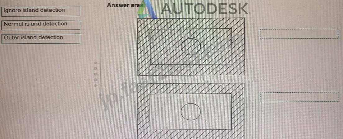
You are using the HATCH command in a drawing. You select the internal point that corresponds with the X as shown in the following exhibit.
Move each setting from the list on the left to the corresponding result on the right.
正解:
解説:
Explanation
Box 1 = ignore island detection
Box 2 = Outer island detection
https://knowledge.autodesk.com/support/autocad/learn-explore/caas/CloudHelp/cloudhelp/2021/ENU/AutoCAD
質問 # 34
You want to print a copy of a floor plan with all the interior objects hidden. You already have a polyline drawn around the footprint of the plan.
Complete the statements by selecting the correct option from the drop-down,lists.

正解:
解説:
Explanation
BOX 1 = WIPEOUT command with the Polyline option2.BOX2 = DRAWORDER command23
https://forums.autodesk.com/t5/autocad-forum/polyline-plan-view-boundary-of-point-cloud/td-p/6251860
質問 # 35
Exhibit
The viewport scales in the title block shown are field value as extracted from the properties of each viewport.
When using the Insert Field command to edit the text value and generate the viewport scale, which object property should you use, if the default scale list is being used?
- A. Display locked
- B. Visual style
- C. Object name
- D. Standard scale
正解:D
解説:
Explanation
The object property that you should use when using the Insert Field command to generate the viewport scale, if the default scale list is being used, is the "Standard scale".
The "Standard scale" property is used to specify the standard scale factor for the viewports. It represents a value in the format of 1:n, where n is the scale factor. For example, if you set the standard scale to 1:50, the viewport will display objects at a scale of 50 units per drawing unit.
To use this property in the Insert Field command, you can select "Object" in the "Field category" dropdown and "Standard scale" from the "Field names" dropdown. This will insert a field code that will automatically update the viewport scale based on the properties of the viewport.
質問 # 36
You need to create a hatch pattern that looks the same regardless of the viewport scale.
What should you do?
- A. Set the current hatch scale by using the HPSCALE system variable
- B. Set the default hatch pattern
- C. Create an associative hatch
- D. Create an annotative hatch
正解:D
解説:
Explanation
an annotative hatch is a hatch that automatically adjusts its scale and size to match the viewport scale. This means that the hatch pattern will look the same regardless of how you zoom in or out of the viewport.
To create an annotative hatch, you need to:
* Set the annotation scale tool to 1:1
* Create your hatch as usual
* In the properties palette, make the hatch annotative
* Add annotation scales to the hatch as needed
This will create a hatch that displays correctly at different viewport scales.
https://forums.autodesk.com/t5/autocad-forum/annotative-hatch/td-p/2651268
質問 # 37
Select whether each statement is True or False.
正解:
解説:
Explanation
True
1. According to the AutoCAD for Design and Drafting documents1, a polyline is a connected sequence of line segments created as a single object. You can create straight line segments, arc segments, or a combination of the two2341. Therefore, the correct answer is True. A polyline can include both straight line segments and arc segments.
2. False.According to the AutoCAD for Design and Drafting documents1, a spline is a smooth curve that passes through or near a set of fit points, or that is defined by the vertices in a control frame. A spline does not have a constant radius, but rather a local radius at each point on the curve2. Therefore, AutoCAD cannot directly dimension or display a radius of a spline curve23. You can use some workarounds such as exploding the curve to arc segments with the FLATTEN command2, or creating a polyline over the top with arc active3, but these may not be accurate or desirable. Therefore, the correct answer is False. The radius on a spline cannot be found in AutoCAD properties.3. TrueAccording to the AutoCAD for Design and Drafting documents1, a 2D polyline is a connected sequence of line segments created as a single object. You can specify an elevation for a 2D polyline using the Edit Polyline Elevations command2. However, this command will assign the same elevation to all vertices of the polyline2. Therefore, you cannot assign different elevations to different segments or points of a 2D polyline. Therefore, the correct answer is True. You can assign only one elevation to a 2D polyline.
質問 # 38
Refer to the exhibit.
This section view was dimensioned using Baseline Dimensions The dimensions are too close together which impacts the drawing's legibility. What is the most efficient method to avoid this problem in the future?
- A. Copy and Paste
- B. Grip Edit
- C. Dimension Style Manager
- D. Move
正解:C
解説:
Explanation
a baseline dimension is a linear, angular, or ordinate dimension that is measured from the baseline of a previous or selected dimension. The spacing between baseline dimensions can be set from the Dimension Style Manager, Lines tab, Baseline Spacing (DIMDLI system variable).
The most efficient method to avoid the problem of dimensions being too close together in the future is to use Dimension Style Manager. This will allow you to change the default spacing for all baseline dimensions in your drawing.
https://knowledge.autodesk.com/support/autocad/learn-explore/caas/CloudHelp/cloudhelp/2015/ENU/AutoCAD
質問 # 39
You are modifying an AutoCAD drawing for a customer.
You would like to bring your customers attention to a specific area of the drawing that you modified for review.
Which type of object is conventionally used?
- A. A viewport
- B. A revision cloud
- C. A solid hatch
- D. A construction line
正解:B
解説:
Explanation
The type of object that is conventionally used for this purpose is D. A revision cloud123. A revision cloud is a way to highlight changes or revisions in a drawing by creating a cloud-shaped polyline around them12. You can create a revision cloud by moving the mouse or by converting existing objects2. You can also change the style, color, layer and properties of the revision cloud13.
質問 # 40
In model space (MODEL), a room label text height is set to 300 mm in the designated text style.
Which viewport scale should you apply to a layout viewport (PAPER) so that the room label text height will display as 3 mm when plotting the drawing?
- A. 100:1
- B. 1:1
- C. A custom viewport scale
- D. 1:100
正解:A
解説:
Explanation
the formula for determining object scaling is:
Object Height x Annotation Scale x Annotation Plot Size = Model Space or Paper Space Height In this case, we want the room label text height to be 3 mm in paper space when plotting the drawing.
Assuming an annotation plot size of 1 mm and an object height of 300 mm, we can solve for the annotation scale as follows:
300 x Annotation Scale x 1 = 3 Annotation Scale = 3 / 300 Annotation Scale = 0.01 Therefore, the viewport scale that corresponds to this annotation scale is B. 100:1.
https://knowledge.autodesk.com/support/autocad-architecture/learn-explore/caas/CloudHelp/cloudhelp/2016/EN
質問 # 41
In which order should you perform the actions to rotate square (1) to match the angle of square (2).
Move all actions to the answer area and place them in the correct order.

正解:
解説:
Explanation
rotate is a command that rotates selected objects around a base point to an absolute angle. You can specify the base point and the rotation angle by entering values or selecting points. You can also use the reference option to align objects with other objects.
* 1- Start the Rotate command, select the square, and press Enter
* 4- Specify the base point
* 5- Select the Reference option
* 3- Select the lower left corner and the lower right corner as the first and second points of the reference angle
* 2- Enter a value of 0 for the new angle and press Enter
質問 # 42
Move three applicable commands from the list on the left to the corresponding function on the right.
Commands may be used once or not at all (Select 3)
正解:
解説:
Explanation
Box 1 : Batch plot
One of the topics covered in this course is Plotting Drawings2. In this topic, you can learn how to print multiple sheets or drawings to a plotter, printer, DWF file, or PDF file. The applicable command for this function is Batch plot (PUBLISH)2.
https://www.autodesk.com/certification/learn/course/autocad-drawing-design-drafting-professional Box 2: EtransmitOne of the topics covered in this course is Sharing Drawings2. In this topic, you can learn how to create a package of drawing files and their dependencies. The applicable command for this function is Etransmit (ETRANSMIT)2.
https://www.autodesk.com/certification/learn/course/autocad-drawing-design-drafting-professional Box3: ExportOne of the topics covered in this course is Exporting Drawings2. In this topic, you can learn how to save the objects in a current drawing to a different file format, such as SAT, STL, etc. The applicable command for this function is Export (EXPORT)2.
https://www-int.autodesk.com/certification/learning-pathways/autocad-design-drafting
質問 # 43
......
リアル問題集で100%無料ACP-01101試験問題集を試そう:https://jp.fast2test.com/ACP-01101-premium-file.html
実際のACP-01101問題集最新練習テスト問題集:https://drive.google.com/open?id=1hITruGtkHXCcIBAY5Ub6nVM37x-EpOV3