

[2025年07月]更新のSupermicro SMI300XS公式認定ガイドPDF
試験SMI300XS Supermicro MI300X GPU Service Specialist (SMI300XS) Exam
質問 # 10
In the motherboard tray, the AOM bracket is partially covered by the support bar. So, you'll need to remove the support bar first before you can remove the AOM bracket. True or False?
- A. True
- B. False
正解:A
解説:
Why Must the Support Bar Be Removed First?
* Thesupport baris areinforcement structureinside the chassis that providesmechanical stabilityto components, including theAOM bracket.
* Since the AOM bracket is partially covered by the support bar, you mustremove the bar firstto gain full access.
Step-by-Step Removal Process:
#Step 1:Remove the screws securing the support bar.#Step 2:Carefully lift and remove the support bar without tilting it.#Step 3:Now, unscrew and remove the AOM bracket.
Why is False Incorrect?
* IfFalse were correct, it would suggest that the AOM bracket can be removedwithout touching the support bar, which isnot possibledue to obstruction.
Official Documentation Reference:
* Supermicro AS-8125GS-TNMR2 Disassembly Manualconfirms that thesupport bar must be removed first before accessing the AOM bracket.
質問 # 11
Why is there a yellow warning label on the flat panel/ribbon cable?
- A. To warn you that the cable is hot.
- B. To warn you that you must remove the flat panel cable after removing the midplane from the chassis or you will damage the cable.
- C. To warn you that you can optionally remove the flat panel cable before removing the midplane from the chassis or you will damage the cable.
- D. To warn you that you must remove the flat panel/ribbon cable before removing the midplane from the chassis or you will damage the cable.
正解:D
解説:
Theyellow warning labelis a critical indicator toprevent damagewhen servicing themidplane and ribbon cable connections.
Reason for Warning Label:
* Theflat panel/ribbon cable is delicateand isconnected between multiple system components.
* If themidplane is removed first, itstretches and applies force on the ribbon cable, leading to:
* Broken cable connectors
* Torn ribbon cable
* System interface failure(front panel controls, LED indicators, or data communication) Why other options are incorrect?
* A (Cable is hot)# Ribbon cablesdo not generate heatand thisis not the purpose of the warning label.
* B (Remove after midplane)# Thecable must be removed BEFORE the midplane, not after.
* C (Optional removal)#It is mandatory, not optional, to prevent damage.
Official Documentation Reference:
* Supermicro AS-8125GS-TNMR2 Maintenance Manualstates thatremoving the flat panel/ribbon cable firstisa required stepbefore handling the midplane.
質問 # 12
What are the components on top of the motherboard in the AS-8125GS-TNMR2 system?(Choose 3 answers)
- A. Fans and fan shrouds
- B. Heatsinks and CPUs
- C. Support bar and AOM brackets
- D. DIMM modules
正解:A、B、C
解説:
Components Located on Top of the Motherboard in Supermicro MI300X Systems
* Fans and Fan Shrouds (Option A)
* These are installedabove the motherboardtodirect airflow over the components.
* Fan shrouds help focus airflow, ensuringefficient cooling of CPUs and GPUs.
* Support Bar and AOM Brackets (Option B)
* Thesupport bar reinforces the motherboard tray, preventing flexing.
* AOM bracketshold optionalnetworking or RAID expansion modules.
* Heatsinks and CPUs (Option C)
* Large heatsinks are mounted on top of the CPUsto dissipate heat.
* These ensureoptimal thermal managementof high-performanceAMD MI300X GPUs and processors.
Why Option D (DIMM Modules) is Incorrect?
#DIMM modules (memory sticks) are installed in slots beside the CPU, but they arenot physically above the motherboardin a way that they could be considered a top-mounted component.
Official Documentation Reference:
* Supermicro AS-8125GS-TNMR2 System Overviewconfirms thatfans, heatsinks, AOM brackets, and support bars are mounted on top of the motherboard.
質問 # 13
Which two situations could occur if you forcefully shift the release lever without first unlocking the red lock?(Choose 2 answers.)
- A. All the answers are correct.
- B. The power supply unit will fail.
- C. You could permanently damage the lock on the power supply unit.
- D. The power supply unit can no longer be secured into the tray.
正解:B、C
解説:
ForSupermicro MI300X GPU systems,removing the power supply unit (PSU) improperlycan lead to serious issues.
* Why the red lock exists?
* Thered locking mechanismensures that thePSU is properly securedin the system.
* Before disengaging the PSU, thered lock must first be unlockedto avoid damage.
* If you forcefully shift the release lever without unlocking the red lock:
* B: The power supply unit will fail# If the PSU is removed improperly, it can causeinternal damageto power connectors, resulting in PSUfailure or improper functioning.
* C: You could permanently damage the lock on the power supply unit# Thelocking mechanismis designed for smooth disengagement. Forcefully shifting the lever canbreak or warpthe lock, making itimpossible to secure the PSU back in place.
* Incorrect Answers Explained:
* A (All answers are correct)# This is incorrect becausenot all answers are valid.
* D (The PSU can no longer be secured into the tray)# This happensonly if the lock is damaged
, which is covered underoption C.
Supermicro's official documentation clearly statesthatunlocking the red lock firstis a critical step before removing or replacing the PSU.
質問 # 14
Exhibit: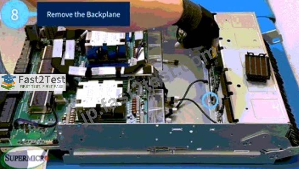
4 screws secure the backplane to the motherboard tray that you will need to remove, and they are spaced equidistant across the backplane. True or False?
- A. True
- B. False
正解:A
解説:
Why Are the Screws Equidistant?
* Thebackplane in Supermicro MI300X systemsis alarge PCB (printed circuit board) that connects NVMe SSDs and PCIe devices to the motherboard.
* It is secured byfour screws placed equidistantlyto:
* Distribute mechanical stress evenly
* Ensure stability against vibrations
* Prevent warping or misalignment of connectors
Proper Removal of the Backplane Screws:
#Step 1:Identify and locate the4 securing screws on the backplane.#Step 2:Loosen them in across-pattern (diagonal pairs) to prevent stress buildup.#Step 3:Carefully lift the backplanestraight upto avoid bending connector pins.
Why This Layout Is Important?
#Equidistant screw spacing ensures even pressure distribution, preventing PCB flexing or cracking.# Improper screw removal (one side first) can cause misalignment or undue stress on connectors.
Why False Is Incorrect?
* IfFalse were correct, it would imply that screws are placedrandomly or unevenly, which isnot the case in Supermicro MI300X systems.
Official Documentation Reference:
* Supermicro AS-8125GS-TNMR2 Installation Manualconfirms thatthe backplane is secured with 4 evenly spaced screws for structural integrity.
質問 # 15
Exhibit: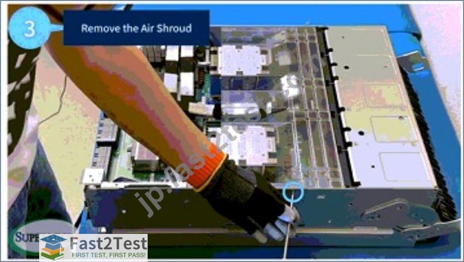
Where are the 2 screws located before you can remove the air shroud?
- A. On top of the motherboard tray
- B. On both sides of the motherboard tray
- C. On both sides of the PCIe tray
- D. On both sides of the GPU tray
正解:B
解説:
Theair shroudis a crucial component in theSupermicro MI300X GPU system, designed todirect airflow efficientlyover high-performance GPUs and CPUs.Before removing the air shroud, two screws must be removed, and they are located on both sides of the motherboard tray.
Why are these screws important?
* They secure the air shroud to the chassis, preventing unwanted movement.
* Removing them ensures the air shroud can be lifted safely, without damaging cooling pathways.
* They prevent vibrations from GPU cooling fans from dislodging the shroud over time.
Incorrect Answers Explained:
* A (On top of the motherboard tray)# Incorrect, as the screws are not mounted on top but on thesides of the motherboard tray.
* C (On both sides of the PCIe tray)# The PCIe tray does not secure the air shroud.
* D (On both sides of the GPU tray)# The GPU tray does not directly hold the air shroud in place.
Official Documentation Reference:
* Supermicro AS-8125GS-TNMR2 Cooling System Guidestates that theair shroud is secured by two screws on both sides of the motherboard tray.
質問 # 16
Once you remove the midplane lid from the AS-8125GS-TNMR2 system, how many total screws must be removed from the sides of the chassis in order to remove the midplane bracket?
- A. 2 screws total (1 on each side of the chassis)
- B. 4 screws total (2 on each side of the chassis)
- C. 6 screws total (3 on each side of the chassis)
- D. 8 screws total (4 on each side of the chassis)
正解:B
解説:
To remove themidplane bracketin theAS-8125GS-TNMR2 system, you must remove4 screws total(2 on each side of the chassis).
Why 4 screws?
* The midplane bracket is secured by 2 screws per sideto maintain its structural integrity.
* Loosening all 4 screws allows safe removal without excessive force.
* Forcing the bracket without removing the screws risks damaging the mounting points.
Incorrect Answers Explained:
* A (2 screws total)# Not enough, as screws on both sides must be removed.
* C (8 screws total)# More than necessary;only 4 screws hold the midplane bracket.
* D (6 screws total)# Incorrect count;only 2 screws per side are required.
Official Documentation Reference:
* Supermicro AS-8125GS-TNMR2 Installation Guideexplicitly states thattwo screws on each side (4 total) must be removed to release the midplane bracket.
質問 # 17
In order to remove the midplane from the AS-8125GS-TNMR2 system, and after you remove all the PSUs, you will need to disengage 3 trays. What is the correct order for disengagement?
- A. Disengage the motherboard tray first, then the PCIe tray, and the GPU tray last.
- B. Disengage the PCIe tray first, then the motherboard tray, and the GPU tray last.
- C. Disengage the PCIe tray first, then the GPU tray, and the motherboard tray last.
- D. Disengage the GPU tray first, then the motherboard tray, and the PCIe tray last.
正解:C
解説:
Thecorrect order for removing trays before midplane removalis:
* Disengage the PCIe tray first
* This tray must be removed first becauseit provides access to the underlying system components
.
* Remove the GPU tray
* TheGPU tray sits between the PCIe and motherboard traysand must be disengaged after PCIe components are cleared.
* Remove the motherboard tray last
* The motherboard tray isthe final component before midplane removal.
* Removing it lastensures full accessto the system componentswithout obstructing critical connections.
Why other options are incorrect?
* B (Motherboard before GPU tray)# The motherboard tray must be removedlastto avoid disconnecting system-critical connections too early.
* C (Motherboard tray first)# Removing the motherboard firstrisks damagingPCIe and GPU components.
* D (GPU tray first)# TheGPU tray is dependent on the PCIe tray being removed first, making this order incorrect.
Official Documentation Reference:
* Supermicro AS-8125GS-TNMR2 System Removal Guideoutlines the correct order fortray disengagement before midplane removal.
質問 # 18
What equipment is required in order to remove the heatsink from the motherboard tray?
- A. PH2 Phillips screwdriver
- B. T30 Torx bit
- C. T20 Torx bit
- D. T40 Torx bit
正解:B
解説:
To remove theheatsink from the motherboard tray,a T30 Torx bit is required. This tool ensuresproper torque applicationandprevents damageto both the heatsink and the motherboard.
Why a T30 Torx bit is necessary?
* Supermicro MI300X GPU systems use precision heatsink retention mechanisms.
* Theheatsink screws are secured with factory torque settingsand require aT30 Torx bitfor safe removal.
* Using an incorrect tool (Phillips screwdriver, T20, or T40) can strip the screw heads, making it difficult to remove the heatsink without causing damage.
Incorrect Answers Explained:
* A (PH2 Phillips screwdriver)# Not strong enough for heatsink screws, which requirehigh torquefor proper seating.
* C (T20 Torx bit)# Toosmall, risksstrippingthe screws.
* D (T40 Torx bit)# Toolarge, does not fit the heatsink screws.
Official Documentation Reference:
* Supermicro MI300X Service Manualspecifies that aT30 Torx bitmust be used to remove the heatsink without damaging the motherboard.
質問 # 19
Why is there a yellow warning label on the flat panel/ribbon cable?
- A. To warn you that the cable is hot.
- B. To warn you that you must remove the flat panel cable after removing the midplane from the chassis or you will damage the cable.
- C. To warn you that you can optionally remove the flat panel cable before removing the midplane from the chassis or you will damage the cable.
- D. To warn you that you must remove the flat panel/ribbon cable before removing the midplane from the chassis or you will damage the cable.
正解:D
質問 # 20
How many screws need to be loosened across the bracket in the bottom of the motherboard tray in front of the backplane?
- A. 0
- B. 1
- C. 2
- D. 3
正解:D
解説:
When servicing theSupermicro MI300X GPU system, there are3 screwssecuring thebracket at the bottom of the motherboard trayin front of the backplane.
Purpose of these screws:
* They secure the backplane's structural integrityto prevent vibration-related failures.
* Loosening them allows the removal or replacement of backplane componentssafely.
* They prevent accidental disconnectionscaused by handling or system movement.
Why other options are incorrect?
* A (13 screws)# This number istoo highfor just the bottom bracket.
* B (21 screws) & C (30 screws)# These numbersapply to entire system disassembly, not just the bottom bracket.
Official Documentation Reference:
* Supermicro AS-8125GS-TNMR2 Disassembly Guidespecifies thatonly 3 screwsneed to be loosened to access thebottom bracket securing the backplane.
質問 # 21
Exhibit: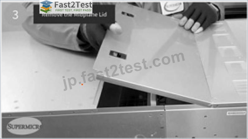
To remove the midplane lid on the AS-8125GS-TNMR2 system, use your fingers to push in on the two handles toward the PCIe tray, then slowly lift the midplane lid up and out of the chassis at an angle.
True or False?
- A. True
- B. False
正解:A
解説:
* Themidplane lid removal processis designed to betool-freeand follows aspecific sequence to avoid damage.
* Thecorrect methodis:
* Push in on the two handleslocated near thePCIe tray.
* Slowly lift the midplane lid up, ensuring it does not catch on other components.
* Remove the lid at an angleto avoid damaging adjacent connectors.
Why this method is used?
* Theangled removalhelpsavoid contact with fragile connectorson the midplane.
* Forcing the lid straight upcould damage PCIe slots or motherboard connectors.
Official Documentation Reference:
* Supermicro AS-8125GS-TNMR2 Disassembly Manualdetails thecorrect method for removing the midplane lid.
質問 # 22
It is essential to connect the purple 5-volt power connector to the correct port to avoid damaging the AS-8125GS-TNMR2 system. True or False?
- A. True
- B. False
正解:A
解説:
Why is the Purple 5V Power Connector Critical?
InSupermicro MI300X systems, thepurple 5V power connectorisresponsible for delivering stable low- voltage powerto specific components.
Consequences of Incorrect Power Connector Placement:
#1. System Failure or Non-Booting State
* If the5V power connector is plugged into the wrong port, the systemmay not receive proper voltage
, leading to failure.
#2. Component Damage
* Overvoltage or incorrect voltage levelsmayfry sensitive system components(e.g., NVMe controllers, PCIe devices).
#3. Risk of Short Circuit
* Plugging the power cable into an incorrect portmay cause short circuits, leading topermanent hardware damage.
Proper Connection Steps:
#Step 1:Identify thepurple 5V connectoron the PSU and NVMe backplane.#Step 2:Match it with the correct
5V porton the system board.#Step 3:Ensure asecure and firm connectionbefore powering the system back on.
Why is False Incorrect?
* IfFalse were correct, it would imply thatincorrectly plugging the power connector has no consequences, which iswrong.
* Supermicroexplicitly warns against incorrect power connectionsdue topotential damage risks.
Official Documentation Reference:
* Supermicro AS-8125GS-TNMR2 Electrical Guidestates thatincorrect power connections can lead to irreversible hardware failure.
質問 # 23
Before removing the midplane from the AS-8125GS-TNMR2, you must disengage all the power supply units (PSUs) and dummy PSUs, as well as the PCIe tray, motherboard tray, and GPU tray. True or False?
- A. True
- B. False
正解:A
解説:
Removing themidplanein aSupermicro MI300X GPU systemrequiresdisengaging multiple system trays and power componentsbeforehand.
Why is this necessary?
* Power must be fully disengaged before midplane removal
* The midplane is directly connected topower distribution units (PDUs).
* If power is not removed, it can causeshort circuits or hardware damage.
* PCIe, motherboard, and GPU trays block access
* These trays must be disengagedbefore removing the midplane, as they contain components directly connected to it.
* Dummy PSUs must also be removed
* Even inactive PSUs containlocking mechanismsthat must be disengaged.
Official Documentation Reference:
* Supermicro AS-8125GS-TNMR2 System Removal Guideconfirms thatPSUs, dummy PSUs, PCIe trays, motherboard trays, and GPU trays must be removed before handling the midplane.
質問 # 24
Which cables need to be reconnected after installing the NVMe backplane?
- A. Only the i2C Cable
- B. Only the SAS Cable
- C. Only the Power Cable
- D. i2C Cable, SAS Cable, Power Cable
正解:D
解説:
NVMe Backplane Connection Requirements in Supermicro MI300X Systems
Afterinstalling the NVMe backplane, the following cablesmust be reconnectedfor proper system functionality:
* i2C Cable(Inter-Integrated Circuit Cable)
* Responsible fordata communication, sensor monitoring, and system management functions.
* Ensures thatstorage devices are properly detectedby the motherboard.
* SAS Cable(Serial Attached SCSI)
* Used forhigh-speed storage connectivityin hybrid NVMe/SAS systems.
* Ensuresdata integrity and fast data transfers between SSDs and the system controller.
* Power Cable
* Supplies power to the NVMe backplaneandconnected drives.
* Without this,NVMe drives will not receive power and will not be detected by the system.
Why Other Options Are Incorrect?
* B (Only the SAS Cable)# While the SAS cable is important,the power cable and i2C cable are also required.
* C (Only the i2C Cable)# The i2C cable isnot sufficient by itself; the NVMe backplaneneeds both power and data connections.
* D (Only the Power Cable)# Power is needed, butdata connectivity through SAS and i2C is essential for full functionality.
Official Documentation Reference:
* Supermicro NVMe Storage System Guideconfirms thati2C, SAS, and power cables must all be reconnected after NVMe backplane installation.
質問 # 25
Exhibit:
What is the proper way to remove the backplane from the motherboard tray?
- A. Ask a data center technician to remove it for you.
- B. Hold the start button and press left and right buttons to get more lives.
- C. Use both hands to tilt the top of the backplane towards you and lift it up and out of the motherboard tray.
- D. Use one hand to grab one side of the motherboard tray and rip the backplane out.
正解:C
解説:
Thecorrect and safemethod to remove the backplane from the motherboard tray is to useboth hands, gently tilting thetop of the backplanetowards yourself while carefullylifting it up and outof the motherboard tray.
This ensures that:
* No undue forceis applied to the connectors or PCB.
* No components or cablesare unintentionally damaged.
* Proper handling of static-sensitive componentsis maintained.
Removing the backplane improperly can result in:
* Connector damageto the motherboard or backplane.
* PCB warping, which could lead to future malfunctions.
* Potential data center downtimedue to component failure.
According toSupermicro's official documentation, this method aligns withindustry best practicesand recommended service proceduresforSupermicro MI300X GPU systems.
質問 # 26
Exhibit: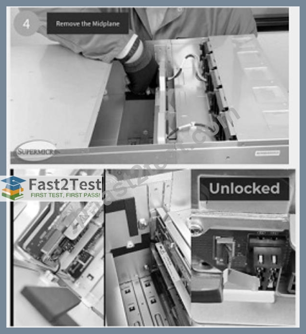
There is a flap door over the ribbon cable connection. To open it, use your finger to press down on the top of the flap door and pop it open. True or False?
- A. True
- B. False
正解:A
解説:
Theflap door mechanismis a protective feature inSupermicro MI300X systemsdesigned tosecure ribbon cable connections.
How to open it correctly?
* Press down on the top of the flap door# This disengages the locking mechanism.
* The flap door will "pop open" safelywithout damaging the ribbon cable.
* Forcing the flap without pressing down properly may break the connector.
Official Documentation Reference:
* Supermicro AS-8125GS-TNMR2 Maintenance Manualprovidesspecific instructionsonpressing down the flap door before opening it.
質問 # 27
When reinstalling the motherboard tray, is it necessary to align it properly with the chassis grooves before securing it with screws? True or False?
- A. True
- B. False
正解:A
解説:
Importance of Proper Alignment in Motherboard Tray Installation
Themotherboard tray in Supermicro MI300X systemsisprecisely designedto fit intopre-existing grooves in the chassis.
* Ensures a Secure Fit
* If the motherboard tray isnot aligned with the grooves, itmay not seat correctly, causing structural instability.
* Prevents Cable Routing Issues
* Improper alignmentcan interfere with airflow and cable routing, leading to cooling inefficiencies.
* Guarantees Proper PCIe and Power Connections
* Misalignmentcan cause PCIe slots and power connectors to be slightly off-position, leading to failed component detection.
Proper Installation Steps for the Motherboard Tray:
#Step 1:Slide the motherboard tray into thechassis groovesfor proper alignment.#Step 2:Ensure it isflush with the chassisbefore securing screws.#Step 3:Tighten screws evenly to prevent misalignment.
Why is False Incorrect?
* IfFalse were correct, it would imply that the motherboard tray can be installedwithout aligning it properly, which isnot possiblein Supermicro MI300X systems.
* The systemwill not function properlyif the motherboard tray is misaligned.
Official Documentation Reference:
* Supermicro AS-8125GS-TNMR2 Service Manualconfirms that themotherboard tray must be aligned with the grooves before securing it with screws.
質問 # 28
......
無料SMI300XS試験問題集試験点数を伸ばそう:https://jp.fast2test.com/SMI300XS-premium-file.html